Скачать с ютуб Cylinder head removal and rebuild 2013 Audi A4 2.0 TFSI в хорошем качестве
Cylinder head removal and rebuild 2013 Audi A4 2.0 TFSI
2 года назад
Скачать бесплатно и смотреть ютуб-видео без блокировок Cylinder head removal and rebuild 2013 Audi A4 2.0 TFSI в качестве 4к (2к / 1080p)
У нас вы можете посмотреть бесплатно Cylinder head removal and rebuild 2013 Audi A4 2.0 TFSI или скачать в максимальном доступном качестве, которое было загружено на ютуб. Для скачивания выберите вариант из формы ниже:
Загрузить музыку / рингтон Cylinder head removal and rebuild 2013 Audi A4 2.0 TFSI в формате MP3:
Если кнопки скачивания не
загрузились
НАЖМИТЕ ЗДЕСЬ или обновите страницу
Если возникают проблемы со скачиванием, пожалуйста напишите в поддержку по адресу внизу
страницы.
Спасибо за использование сервиса savevideohd.ru
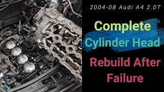
Cylinder head removal and rebuild 2013 Audi A4 2.0 TFSI
How to remove the cylinder head and rebuild it on a 2013 Audi A4 Quattro 2.0TFSI with Torque specs and sequences. Vw/ Audi Sealant is Loctite brand 5970 Cylinder Head, Valvetrain – 2.0L CAEB, CPMA Fastener Tightening Specifications Component Nm Balance shaft timing chain guide rail 20 Bearing bracket 1) 3) 9 20 plus an additional 90° (¼ turn) Camshaft adjuster actuator 5 Camshaft Position (CMP) sensor 9 Camshaft timing chain guide rail guide pins 20 Chain tensioner 4) 9 Chain tensioner 2) 85 Control valve-to-camshaft housing 35 Cylinder head with wrench clearance 1) 5) Tighten in 3 stages: • Tighten to 40 Nm • Tighten 90° further using a rigid wrench. • Tighten 90° further using a rigid wrench. Tighten in 2 stages: • Tighten to 8 Nm • Tighten 90° further using a rigid wrench. Exhaust side balance shaft 1) 9 Heat shield 20 Intake side balance shaft 1) 9 Mounting plate 9 Oil dipstick guide tube-to-timing chain cover 9 Plug with ball head for the engine cover 5 Sealing plugs with ball head for the engine cover 9 Sealing plugs with ball head for the engine cover 5 Timing chain tensioning rail 20 Timing chain tensioning rail guide pins 20 Transport bracket 25 1) Replace fastener(s). 2) For bolt tightening clarification, refer to ElsaWeb, Balance Shaft Timing Chain Overview, item 4. 3) For bolt tightening clarification, refer to ElsaWeb, Camshaft Timing Chain Overview, items 5 and 7. 4) For bolt tightening clarification, refer to ElsaWeb, Camshaft Timing Chain Overview, and item 2. 5) For bolt tightening clarification, refer to ElsaWeb, Cylinder Head Overview, with Wrench Clearance“ items 4 and 6. Component Nm Adapter between connecting piece and high pressure fuel line 40 Air duct-to-lock carrier 2 Cold start injector 10 E-Box cover 3.5 Engine Speed (RPM) sensor 4.5 Fuel pressure sensor 27 Fuel rail to intake manifold 10 Fuel supply line connectors 1) 40 Fuel supply line connection on the fuel rail 1) 40 Fuel supply line union nut 20 High pressure fuel line 27 High pressure fuel line to adapter 20 High pressure pump First tighten the bolts diagonally hand-tight, then to 5 Nm and then to 20 Nm. 20 Intake air temperature sensor 9 Intake manifold 9 Intake manifold support nut 10 Intake manifold support bolt 23 Knock Sensor (KS) 20 Oxygen Sensors (O2S) 55 Throttle valve control module 10 1) Replace fastener(s).
Comments