Скачать с ютуб Analog Output Measurement | Measure 4 to 20 mA DC current of DP Transmitter в хорошем качестве
Analog Output Measurement | Measure 4 to 20 mA DC current of DP Transmitter
3 года назад
Скачать бесплатно и смотреть ютуб-видео без блокировок Analog Output Measurement | Measure 4 to 20 mA DC current of DP Transmitter в качестве 4к (2к / 1080p)
У нас вы можете посмотреть бесплатно Analog Output Measurement | Measure 4 to 20 mA DC current of DP Transmitter или скачать в максимальном доступном качестве, которое было загружено на ютуб. Для скачивания выберите вариант из формы ниже:
Загрузить музыку / рингтон Analog Output Measurement | Measure 4 to 20 mA DC current of DP Transmitter в формате MP3:
Если кнопки скачивания не
загрузились
НАЖМИТЕ ЗДЕСЬ или обновите страницу
Если возникают проблемы со скачиванием, пожалуйста напишите в поддержку по адресу внизу
страницы.
Спасибо за использование сервиса savevideohd.ru
Analog Output Measurement | Measure 4 to 20 mA DC current of DP Transmitter
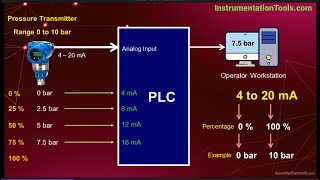
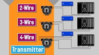
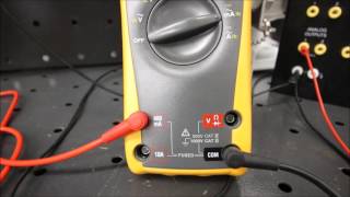
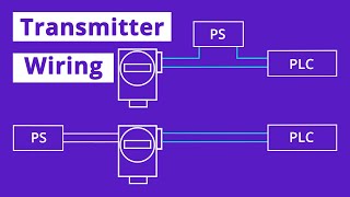
In this video, I have shown two different methods to measure 4 to 20 mA analog output current of Pressure Transmitter, DP Transmitter, Level Transmitter & Temperature Transmitter _ _ _ _ _ _ _ _ _ _ _ _ _ _ _ _ _ _ _ _ _ _ _ _ _ _ _ _ _ _ _ _ _ Video content: 1. Different methods to measure analog output current of transmitter. In First method, we need to connect multi meter in series with transmitter. As you can see from the diagram, put multimeter in current measuring mode. To put multi meter in current measuring mode, connect red probe to 400 mA port, and black probe to common port of multi meter. After this, rotate the knob of multi meter in clockwise direction, and select ma function. After this, press yellow button at once to select milli ampere dc function. Analog current output can be measured in dc form. So, it is important to select milli ampere dc function. Once you have put multi meter in current measuring mode, connect red probe to negative terminal of transmitter, and common probe to negative terminal of 24 volt dc power supply. Now, multi meter in series with transmitter. So it will show 4 mA in normal condition. And analog current value keep increasing, when measured value increases. In second method, we need to connect multimeter probe to negative terminal and test terminal of transmitter. As you can see from the diagram, this method is only applicable for transmitter, which has test port. In order to measure output current, we need to connect red probe to negative terminal of transmitter, and common or black probe to test terminal. After connecting probe to negative and test terminals, put the multi meter to current measuring mode. And select mA dc function of multi meter. Once you select mA dc from multi meter, multi meter will show mA output of transmitter. _ _ _ _ _ _ _ _ _ _ _ _ _ _ _ _ _ _ _ _ _ _ _ _ _ _ _ _ _ _ _ If you have missed our most recent videos, then watch them here: 1. What is a PID Controller | Proportional Band | Integral Action | Derivative Action • What is a PID Controller | Proportion... 2. What is Direct Action and Reverse Action - Understanding Process Controller Action • What is Direct Action and Reverse Act... 3. What is Closed Loop Control System and Open Loop Control System • What is Closed Loop Control System a... 4. How to perform Kurz Thermal Mass Flowmeter Calibration • How to perform Kurz Thermal Mass Flow... _ _ _ _ _ _ _ _ _ _ _ _ _ _ _ _ _ _ _ _ _ _ _ _ _ _ _ _ _ _ _ _ Keep Supporting us. || LIKE || COMMENT || SUBSCRIBE _ _ _ _ _ _ _ _ _ _ _ _ _ _ _ _ _ _ _ _ _ _ _ _ _ _ _ _ _ _ _ _ #analog_output_devices #analog_output_cable #analog_output_module #analog_output_examples #analog_output #analog_output_current #output_mA #analog_output_wiring
Comments