Скачать с ютуб Low Voltage Regulator Circuit Design with Op Amp, Zener Diode, JFET, BJT Transistors в хорошем качестве
Low Voltage Regulator Circuit Design with Op Amp, Zener Diode, JFET, BJT Transistors
7 месяцев назад
Скачать бесплатно и смотреть ютуб-видео без блокировок Low Voltage Regulator Circuit Design with Op Amp, Zener Diode, JFET, BJT Transistors в качестве 4к (2к / 1080p)
У нас вы можете посмотреть бесплатно Low Voltage Regulator Circuit Design with Op Amp, Zener Diode, JFET, BJT Transistors или скачать в максимальном доступном качестве, которое было загружено на ютуб. Для скачивания выберите вариант из формы ниже:
Загрузить музыку / рингтон Low Voltage Regulator Circuit Design with Op Amp, Zener Diode, JFET, BJT Transistors в формате MP3:
Если кнопки скачивания не
загрузились
НАЖМИТЕ ЗДЕСЬ или обновите страницу
Если возникают проблемы со скачиванием, пожалуйста напишите в поддержку по адресу внизу
страницы.
Спасибо за использование сервиса savevideohd.ru
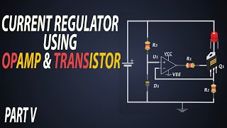
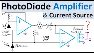
Low Voltage Regulator Circuit Design with Op Amp, Zener Diode, JFET, BJT Transistors
How to design a Low-Voltage Regulator? How does the regulator analog circuit work? How should we select the circuit components? How does temperature compensation work in this circuit? These questions are discussed in this low voltage supply regulator analog circuit design using an example implementation of 2-volt regulated supply at the output of the circuit given an unregulated supply voltage at the input. This circuit is implemented with one operational amplifier, on Zener Diode, one N-channel JFET or Junction Field Effect Transistor, one low-current NPN BJT and one high current PNP Bipolar Junction Transistors. The NPN BJT transistor is wired to operate as a PN junction diode. The negative feedback for op amp circuit is intuitively analyzed and shown that virtual short is enforced for the positive and negative input terminals of the OpAmp. Example of potential choices for op amps are Texas Instruments OPAx607 or THS4051 or analog devices LM108 or more recent FET input op amps with low offset current and noise. The choice of Zener Diode is discussed with temperature coefficient of nearly -0.085% per degree Kelvin. It is recommended to have 1% tolerance resistors (or better) in this circuit.
Comments