–°–∫–∞—á–∞—Ç—å —Å —é—Ç—É–± LED Thermometer with LM35 & LM3914 - PCB Tutorial –≤ —Ö–æ—Ä–æ—à–µ–º –∫–∞—á–µ—Å—Ç–≤–µ
LED Thermometer with LM35 & LM3914 - PCB Tutorial
4 –≥–æ–¥–∞ –Ω–∞–∑–∞–¥
–°–∫–∞—á–∞—Ç—å –±–µ—Å–ø–ª–∞—Ç–Ω–æ –∏ —Å–º–æ—Ç—Ä–µ—Ç—å —é—Ç—É–±-–≤–∏–¥–µ–æ –±–µ–∑ –±–ª–æ–∫–∏—Ä–æ–≤–æ–∫ LED Thermometer with LM35 & LM3914 - PCB Tutorial –≤ –∫–∞—á–µ—Å—Ç–≤–µ 4–∫ (2–∫ / 1080p)
–£ –Ω–∞—Å –≤—ã –º–æ–∂–µ—Ç–µ –ø–æ—Å–º–æ—Ç—Ä–µ—Ç—å –±–µ—Å–ø–ª–∞—Ç–Ω–æ LED Thermometer with LM35 & LM3914 - PCB Tutorial –∏–ª–∏ —Å–∫–∞—á–∞—Ç—å –≤ –º–∞–∫—Å–∏–º–∞–ª—å–Ω–æ–º –¥–æ—Å—Ç—É–ø–Ω–æ–º –∫–∞—á–µ—Å—Ç–≤–µ, –∫–æ—Ç–æ—Ä–æ–µ –±—ã–ª–æ –∑–∞–≥—Ä—É–∂–µ–Ω–æ –Ω–∞ —é—Ç—É–±. –î–ª—è —Å–∫–∞—á–∏–≤–∞–Ω–∏—è –≤—ã–±–µ—Ä–∏—Ç–µ –≤–∞—Ä–∏–∞–Ω—Ç –∏–∑ —Ñ–æ—Ä–º—ã –Ω–∏–∂–µ:
–ó–∞–≥—Ä—É–∑–∏—Ç—å –º—É–∑—ã–∫—É / —Ä–∏–Ω–≥—Ç–æ–Ω LED Thermometer with LM35 & LM3914 - PCB Tutorial –≤ —Ñ–æ—Ä–º–∞—Ç–µ MP3:
–ï—Å–ª–∏ –∫–Ω–æ–ø–∫–∏ —Å–∫–∞—á–∏–≤–∞–Ω–∏—è –Ω–µ
–∑–∞–≥—Ä—É–∑–∏–ª–∏—Å—å
–ù–ê–ñ–ú–ò–¢–ï –ó–î–ï–°–¨ –∏–ª–∏ –æ–±–Ω–æ–≤–∏—Ç–µ —Å—Ç—Ä–∞–Ω–∏—Ü—É
–ï—Å–ª–∏ –≤–æ–∑–Ω–∏–∫–∞—é—Ç –ø—Ä–æ–±–ª–µ–º—ã —Å–æ —Å–∫–∞—á–∏–≤–∞–Ω–∏–µ–º, –ø–æ–∂–∞–ª—É–π—Å—Ç–∞ –Ω–∞–ø–∏—à–∏—Ç–µ –≤ –ø–æ–¥–¥–µ—Ä–∂–∫—É –ø–æ –∞–¥—Ä–µ—Å—É –≤–Ω–∏–∑—É
—Å—Ç—Ä–∞–Ω–∏—Ü—ã.
–°–ø–∞—Å–∏–±–æ –∑–∞ –∏—Å–ø–æ–ª—å–∑–æ–≤–∞–Ω–∏–µ —Å–µ—Ä–≤–∏—Å–∞ savevideohd.ru
LED Thermometer with LM35 & LM3914 - PCB Tutorial
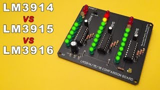
‚ñÝ JLCPCB Prototype for $2(Any Color):¬Ýhttps://jlcpcb.com This is a wide range LED Thermometer, it can be used for measuring temperatures between 0 and 150¬∞C Celsius! - The sensor that mounts is an LM35 while driving the LEDs is an LM3914, all with a five color scale. As you can see the in the circuit diagram, output of the LM35 is connected to the input of the LM3914, and there is also a 47K trimmer through which to make small adjustments of the instrument. The LM35 output is a voltage signal (V+) and varies with temperature variation, directly calibrated in ¬∞C Celsius. After trying the excellent service offered by JLCPCB I recommend it, the quality of the PCB is high, customer service is always available and professional, the time of realization is short and the delivery of PCBs is by express courier. JLCPCB is a great place to get hight quality custom circuit boards at an extremely low price, you can buy 5 PCB Boards (Any Color) for 2$ !!! More About JLCPCB: https://support.jlcpcb.com/collection... Components: - 1x LM3914 IC [ http://bit.ly/2uGBeOt ] - 1x LM35 Temperature Sensor [ http://bit.ly/2ta3qsC ] - 1x 100K Trimmer - 2x 1K resistor - 1x 18K Resistor - 1x 10K resistor - 10x 5mm LED (3 Blue, 2 Green, 2 Yellow, 1 Orange, 2 Red) - 1x 3mm LED (as pwr LED - any color) - 1x DIP 18 Pin - PCB: (Ready for jlcpcb.com): http://bit.ly/2RF4luA *Don't use my PCB for profit or sponsored videos. HD Photos - http://bit.ly/31f59ti - http://bit.ly/3aVCON0 - http://bit.ly/2Oj0Est This circuit must be powered with 5V DC, below I leave the references to view: the electronic circuit diagram, the PCB and the Gerber file to be uploaded directly on the JLCPCB website. - Circuit Diagram: See at: 0:28 - Gerber Files (Ready for jlcpcb.com): http://bit.ly/2RF4luA *You can see the complete procedure to upload the Gerber file on jlcpcb.com in the video from 1:45 **JLCPCB have a Technical Support for exporting Gerber files from many software at this link: https://support.jlcpcb.com/category/2... For any other questions you can ask me for explanations in the video comments:) ‚ñ∫ Subscribe to my Channel: ¬Ý¬Ý¬Ý/¬Ýstefano91ste¬Ý¬Ý Music: "Affectus" by Vexento "Devotion" by Vexento ‚ñÝ‚ñ¨‚ñ¨‚ñ¨‚ñ¨‚ñ¨ LINK & Support ‚ñ¨‚ñ¨‚ñ¨‚ñ¨‚ñ¨‚ñÝ Watch another video =) ‚óè Music Keyboard: ¬Ý¬Ý¬Ý‚Ä¢¬ÝMusic¬ÝKeyboard¬Ýwith¬ÝNE555¬ÝPCB¬ÝTutorial¬Ý¬Ý ‚óè Water Level indicator: ¬Ý¬Ý¬Ý‚Ä¢¬ÝLED¬ÝWater¬ÝLevel¬Ýindicator¬ÝPCB¬ÝTutorial¬Ý¬Ý ‚óè Police Light: ¬Ý¬Ý¬Ý‚Ä¢¬ÝPolice¬ÝLight¬ÝDIY¬Ýwith¬ÝNE555¬Ý-¬ÝPCB¬ÝTut...¬Ý¬Ý ‚óè Electric Field Detector: ¬Ý¬Ý¬Ý‚Ä¢¬ÝHow¬Ýto¬Ýmake¬Ýan¬ÝElectrostatic¬ÝPolarity...¬Ý¬Ý ‚óè Vu-Meter Stereo: ¬Ý¬Ý¬Ý‚Ä¢¬ÝVu-Meter¬ÝStereo¬Ý-20¬Ý+3dB¬ÝLM3916¬Ý-¬ÝPCB...¬Ý¬Ý ‚óè Traffic Light: ¬Ý¬Ý¬Ý‚Ä¢¬ÝMake¬Ýyour¬Ýown¬ÝTraffic¬ÝLight¬Ýon¬ÝPCB¬Ý-¬Ý...¬Ý¬Ý ‚óè Vu-Meter 40 LED: ¬Ý¬Ý¬Ý‚Ä¢¬ÝVu-Meter¬Ý40¬ÝLED¬Ýon¬ÝPCB¬Ýwith¬ÝLM3915¬ÝTU...¬Ý¬Ý ‚óè Automatic LED Light: ¬Ý¬Ý¬Ý‚Ä¢¬ÝAutomatic¬ÝLED¬ÝLight¬Ý(¬ÝLDR¬ÝSensor¬Ý)¬ÝPC...¬Ý¬Ý ‚óè Voltage Detector: ¬Ý¬Ý¬Ý‚Ä¢¬ÝAC¬ÝVoltage¬ÝDetector¬ÝDIY¬Ý-¬ÝPCB¬ÝTutorial¬Ý¬Ý ‚óè Music LED with TIP31: ¬Ý¬Ý¬Ý‚Ä¢¬ÝMake¬ÝMusic¬ÝLED¬Ýwith¬ÝTIP31¬Ýand¬ÝJLCPCB¬Ý...¬Ý¬Ý ‚óè NE555 Signal Generator: ¬Ý¬Ý¬Ý‚Ä¢¬ÝNE555¬ÝSignal¬ÝGenerator¬ÝTutorial¬ÝPCB¬Ý-...¬Ý¬Ý Follow me ‚ô• - YouTube: ¬Ý¬Ý¬Ý/¬Ýstefano91ste¬Ý¬Ý - Instagram: ¬Ý¬Ý/¬Ýstefano91ste¬Ý¬Ý - Pinterest: https://www.pinterest.it/Stefano91ste ‚ñÝ If you'd like to support the channel: Like, Subscribe, Comment and Share my Videos :) ‚ñÝ Do you want to Make a PCB? Look this: ¬Ý¬Ý¬Ý‚Ä¢¬ÝVu-Meter¬ÝStereo¬Ý-20¬Ý+3dB¬ÝLM3916¬Ý-¬ÝPCB...¬Ý¬Ý WARNING: This video is only for demonstration. I don't take any responsibility for damage to things, people and animals. #LM35 #LM3914 #Thermometer
Comments