Скачать с ютуб Universal Heat Pump Defrost Board Install в хорошем качестве
Universal Heat Pump Defrost Board Install
1 год назад
47D01U-843
White-Rodgers
Universal
Defrost Board
Carrier
hvac school
defrost control
heat pump troubleshooting
lockout thermostat
coil temperature sensor
defrost cycle
Emerson
hvac training
heat pump defrost
frozen heat pump
defrost control board
thermostat wiring
defrost temperature sensor
wiring
Install
hvac
Heat Pump
Bert
single-stage
OEM parts
time
temperature
LED
short-cycle
brownout
protection
self-tapping
screws
low voltage wiring
system
Wire nuts
hVACR
Скачать бесплатно и смотреть ютуб-видео без блокировок Universal Heat Pump Defrost Board Install в качестве 4к (2к / 1080p)
У нас вы можете посмотреть бесплатно Universal Heat Pump Defrost Board Install или скачать в максимальном доступном качестве, которое было загружено на ютуб. Для скачивания выберите вариант из формы ниже:
Загрузить музыку / рингтон Universal Heat Pump Defrost Board Install в формате MP3:
Если кнопки скачивания не
загрузились
НАЖМИТЕ ЗДЕСЬ или обновите страницу
Если возникают проблемы со скачиванием, пожалуйста напишите в поддержку по адресу внизу
страницы.
Спасибо за использование сервиса savevideohd.ru
Universal Heat Pump Defrost Board Install
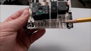
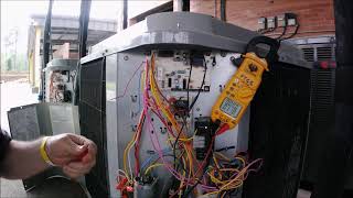
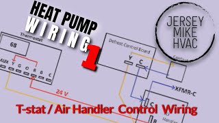
Bert installs the Emerson White-Rodgers Universal Heat Pump Defrost Board (47D01U-843) on a Carrier heat pump. It is a single-stage universal defrost control that replaces a wide range of OEM parts and can be configured to do time/temperature or demand defrost. The Emerson White-Rodgers single-stage universal defrost board comes with the outdoor temperature lockout thermostat, an LED display, short-cycle and brownout protection, self-tapping screws, and sensors in the box. It also has error code recall, so you can see recent error codes. The cross-reference chart is located on the packaging and contains several brands and model numbers. Bert starts by plugging in the thermostat wiring, outdoor temperature sensor, and coil temperature sensor to the board straight out of the box. Before working on the unit, he makes sure the power is off. Then, he takes a picture of the layout so that he can remember how the wiring is configured and what the OEM board's orientation was. In some cases, the OEM will have a thermostat sensor that will be rendered obsolete by the outdoor and coil temperature sensors of the Emerson White-Rodgers universal board. He then mounts the board with the self-tapping screws to secure the board in the best possible orientation. With the board in place, Bert secures the unit's thermostat wires to the corresponding wires on the board with wire nuts. The board allows you to stop the thermostat from bringing on auxiliary heat in some scenarios, so you can break the auxiliary heat signal through the defrost board; you would include the brown wire at the WIN terminal. Otherwise, you would just secure the white wire at the WDX2 terminal under the wire nut. With the low-voltage wiring hooked up, Bert begins wiring the safeties, contactor, and reversing valve. He uses wire nuts on those connections as well, though male spades may also be used. There is also a loss of charge pressure switch in the circuit, which hooks up to the low-pressure switches and will open when there are conditions that resemble low refrigerant charge. Bert makes sure that the fan relay is wired so that it is energized constantly with the high voltage. Then, Bert puts the sensors in optimal locations; the outdoor temperature sensor should be away from direct sunlight, and the coil sensor should make contact with the coil. When everything is in place, Bert cleans up his wiring with some zip ties. With the board fully wired in, Bert restores the low-voltage control power. The board flashes H, indicating that it's in heat (H) and in time delay (flashing). He cancels any calls for heating and cooling and goes through the options until he reaches OE, which allows him to configure the board to match the original manufacturer's defrost cycle. He sets it to 1, which is the setting for Carrier units, and describes the various manufacturer settings compared to the default Emerson White-Rodgers settings. The customizable codes on the LED display include Er (error), Fr (fault recall), OE (quick setup), and then the individual configuration options: dF (defrost type), Et (enable temperature), tt (termination temperature), SS (short-cycle time), r (reversing valve power), Sd (reversing valve shift delay), dt (maximum defrost time), hL (auxiliary heat lockout), Lt (low-temperature compressor cutout), rt (random start delay), LP (low-pressure switch on/off), HP (high-pressure switch on/off), and Bo (brownout protection on/off). Then, Bert tests the system operation to make sure the heat pump will actually switch to defrost mode; he bypasses the time delay and forces defrost. He also runs the unit and heat mode without the fan to cause frost to appear on the coil, which causes the unit to go into defrost by shifting into cooling mode and sending hot discharge gas through the coil. When you're working on systems with these defrost boards, Bert recommends doing a visual inspection and testing the sensors by ohming them out. Check out our recent video all about heat pump defrost at • Learn Everything About Heat Pump Defrost . Buy your virtual tickets or learn more about the 4th Annual HVACR Training Symposium at https://hvacrschool.com/symposium. Read all the tech tips, take the quizzes, and find our handy calculators at https://www.hvacrschool.com/.
Comments