Скачать с ютуб How Transistors Work - The Learning Circuit в хорошем качестве
How Transistors Work - The Learning Circuit
5 лет назад
Скачать бесплатно и смотреть ютуб-видео без блокировок How Transistors Work - The Learning Circuit в качестве 4к (2к / 1080p)
У нас вы можете посмотреть бесплатно How Transistors Work - The Learning Circuit или скачать в максимальном доступном качестве, которое было загружено на ютуб. Для скачивания выберите вариант из формы ниже:
Загрузить музыку / рингтон How Transistors Work - The Learning Circuit в формате MP3:
Если кнопки скачивания не
загрузились
НАЖМИТЕ ЗДЕСЬ или обновите страницу
Если возникают проблемы со скачиванием, пожалуйста напишите в поддержку по адресу внизу
страницы.
Спасибо за использование сервиса savevideohd.ru
How Transistors Work - The Learning Circuit
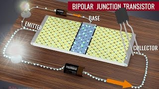
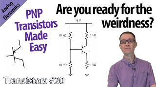
Rather than using a physical, mechanical switch, a transistor can act as an electronic switch, using signals to turn it on or off. Karen goes over what transistors are, how they work, and some different types of transistors: Bipololar junction transistors (BJT), NPN transistors, PNP transistors, and darlington transistors. Connect with Karen on element14: http://bit.ly/2EASjxT Visit The Learning Circuit: http://bit.ly/2OIkbEQ Visit element14 presents: http://bit.ly/2PNXo7d Visit Project14: http://bit.ly/2PPrjfk Previously, we’ve talked about how diodes work. Silicon diodes have a p-n junction. Bipolar junction transistors or BJTs are bipolar because they have two p-n junctions. BJTs are essentially two diodes in a single package. The two main types are NPN and PNP transistors. NPN transistors have two n-type regions on either side of one p-type region, while PNP transistors have two p-type regions, on either side of one n-type region. Bipolar transistors have 3 leads, one going to each region. Typically, the middle layer is the base. P-type in an NPN, and n-type in a PNP. One of the other layers form the emitter and the third, the collector. These are labelled B, E, and C. On the circuit symbol, the arrow is always on the emitter, so we can tell which lead is the emitter and which is the collector by seeing which one has the arrow. The NPN transistor symbol has an arrow on the emitter pointing out, while the PNP transistor symbol has an arrow on the emitter pointing in. Transistors act as an electronic switch, conducting current across the collector-emitter path when a voltage is applied to the base. The switch is off if there is no base voltage present. When base voltage is present, the switch is on. We know from our diodes lesson, that diodes require a forward voltage of 0.7V before they are turned "on" allowing current to flow. In a standard NPN transistor, when 0.7V is applied between the base and the emitter, the transistor “turns ON”, allowing current to flow from the collector to the emitter. With an NPN transistor, we normally bias the device so that the collector voltage is positive with respect to the emitter. The voltage across these two points is referred to as the Collector-Emitter Voltage or VCE. If you connect the base to be positive with respect to the emitter, the voltage is referred to as the Base-Emitter voltage, or VBE. For a PNP transistor, rather than needing a minimum of 0.7V on the base of the transistor, there needs to be a minimum difference of 0.7V between the VCE, collector-emitter voltage, and VBE, base-emitter voltage. If the circuit power supply is a 9V battery, the base-emitter voltage would need to be no more than 8.3V for the transistor to turn “on” and allow current to flow between the collector and emitter. If the base-emitter voltage is 8.6V, a difference of 0.4V, the transistor would be off and no current would flow. If the base-emitter voltage is 7V, the difference of 2V is greater than 0.7V so the transistor would be “on”, allowing current to flow between the emitter and collector.
Comments