Скачать с ютуб Linear Power Supply Circuit [LM317, LM337, Adjustable & Low Noise] в хорошем качестве
Linear Power Supply Circuit [LM317, LM337, Adjustable & Low Noise]
4 года назад
Скачать бесплатно и смотреть ютуб-видео без блокировок Linear Power Supply Circuit [LM317, LM337, Adjustable & Low Noise] в качестве 4к (2к / 1080p)
У нас вы можете посмотреть бесплатно Linear Power Supply Circuit [LM317, LM337, Adjustable & Low Noise] или скачать в максимальном доступном качестве, которое было загружено на ютуб. Для скачивания выберите вариант из формы ниже:
Загрузить музыку / рингтон Linear Power Supply Circuit [LM317, LM337, Adjustable & Low Noise] в формате MP3:
Если кнопки скачивания не
загрузились
НАЖМИТЕ ЗДЕСЬ или обновите страницу
Если возникают проблемы со скачиванием, пожалуйста напишите в поддержку по адресу внизу
страницы.
Спасибо за использование сервиса savevideohd.ru
Linear Power Supply Circuit [LM317, LM337, Adjustable & Low Noise]
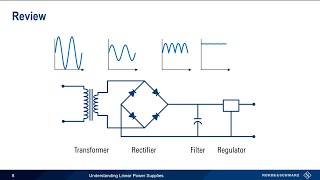
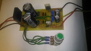
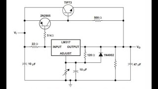
Linear Power Supply Circuit [LM317, LM337, Adjustable & Low Noise] A single-output transformer ============================================= Article Source: https://www.pcbway.com/blog/technolog... ============================================= Support me on Patreon: / myvanitar ============================================= Check other videos: http://bit.ly/2N9OlPa ============================================= Features: AC – DC Conversion Double output voltages (Positive – Ground – Negative) Adjustable positive and negative rails Just a Single-Output AC transformer Output noise (20MHz-BWL, no load): Around 1.12mVpp Low noise and stable outputs (ideal to power Opamps) Output Voltage: +/-1.25V to +/-25V Maximum output current: 300mA to 500mA Cheap and easy to solder (all component packages are DIP) A double output low noise power supply is an essential tool for any electronics enthusiast. There are many circumstances that a double-output power supply is necessary such as designing pre-amplifiers and powering OPAMPs. In this article, we are going to build a linear power supply that a user can adjust its positive and negative rails independently. Moreover, just an ordinary single-output AC transformer is used at the input.D1 and D2 are rectifier diodes. C1 and C2 build the first noise reduction filter stage. R1, R2, C1, C2, C3, C4, C5, and C6 build a low pass RC filter which reduces noise from both positive and negative rails. The behavior of this filter can be examined both in theory and practice. An oscilloscope with a bode plot feature can perform these measurements, such as a Siglent SDS1104X-E.IC1 [1] and IC2 [2] are the main regulation components of this circuit. According to the IC1 (LM317) datasheet: “The LM317 device is an adjustable three-terminal positive-voltage regulator capable of supplying more than 1.5 A over an output-voltage range of 1.25 V to 37 V. It requires only two external resistors to set the output voltage. The device features a typical line regulation of 0.01% and a typical load regulation of 0.1%. It includes current limiting, thermal overload protection, and safe operating area protection. Overload protection remains functional even if the ADJUST terminal is disconnected”.As it is clear, this regulator introduces good line and load regulation figures, therefore we can expect to get a stable output rail. This is identical to the IC2 (LM337). The only difference is that this chip is used to regulate the negative voltages.D3 and D4 are used for protection. The diodes provide a low-impedance discharge path to prevent the capacitors (C9 and C10) from discharging into the output of the regulators.R4 and R5 are used to adjust the output voltages. C7, C8, C9, and C10 are used to filter the remained output noises. #adjustable_power_supply #LM317 #LM337
Comments

![30V-4A Adjustable Power Supply Circuit [CV, CC]](https://i.ytimg.com/vi/0hd9YqLyfBg/mqdefault.jpg)