Скачать с ютуб How to Replace the Rear Upper Control Arms on a Volvo C30 S40 V50 C70 в хорошем качестве
How to Replace the Rear Upper Control Arms on a Volvo C30 S40 V50 C70
5 лет назад
Скачать бесплатно и смотреть ютуб-видео без блокировок How to Replace the Rear Upper Control Arms on a Volvo C30 S40 V50 C70 в качестве 4к (2к / 1080p)
У нас вы можете посмотреть бесплатно How to Replace the Rear Upper Control Arms on a Volvo C30 S40 V50 C70 или скачать в максимальном доступном качестве, которое было загружено на ютуб. Для скачивания выберите вариант из формы ниже:
Загрузить музыку / рингтон How to Replace the Rear Upper Control Arms on a Volvo C30 S40 V50 C70 в формате MP3:
Если кнопки скачивания не
загрузились
НАЖМИТЕ ЗДЕСЬ или обновите страницу
Если возникают проблемы со скачиванием, пожалуйста напишите в поддержку по адресу внизу
страницы.
Спасибо за использование сервиса savevideohd.ru
How to Replace the Rear Upper Control Arms on a Volvo C30 S40 V50 C70
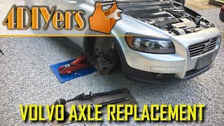
How to replace the upper control arms for the rear suspension on a Volvo C30. This is a 2007 model and the same procedure can also be used on the Volvo S40, V50, and C70 models of the same generation. Worn control arm bushings will cause excessive inner tire wear and when inspecting the bushings, you’ll notice rubber deterioration such as cracking. This car currently has 140,000km and as far as I know, these are the original control arms. #volvo #volvoc30 #volvos40 AutoPartsWay (CA): https://www.autopartsway.ca/partdetai... AutoPartsWay (US): https://www.autopartsway.com/partdeta... Website: http://4diyers.com Patreon: / 4diyers Facebook: / 4diyers Google Plus: https://plus.google.com/+4DIYers Twitter: / 4diyers Instagram: / 4diyers Tumblr: / 4diyers Pintrest: / 4diyers Tools/Supplies Needed: -1/2" drive ratchet -1/2" drive 10" and 5" extension -1/2" drive 15mm socket -15mm wrench -T25 torx driver -penetrating oil -new control arms -torque wrench -wheel wrench -jack and jack stands Procedure: Start by safety jacking up the vehicle and remove the rear wheel. Place a jack stand under the subframe. The upper control arm is only held in with two 15mm bolts, on the side with the fuel filler neck is the hard. There is a module which is held on with 3 T25 torx screws. You’ll need to bend the bracket slightly to access the bolt. In order to access that bolt, you’ll need a 5” and 10” extension with the socket and 1/2” drive ratchet. The bracket can be bent out towards the wheel and you can see the socket in behind the bracket. The module has been pushed up so the extensions runs underneath it. Gloves are recommended, many components are sharp such as the heat shields and some suspension components. Don’t remove that upper bolt just yet as there is tension on the control arm. Remove the bolt on the wheel carrier first. Using a 15mm socket and ratchet, remove this bolt. The rubber flex line for the brakes is also held on the same bolt. If you are finding the bolt binding, there is threadlocker installed from factory, you can work the bolt back and forth to break it loose. Penetrating oil can also be used here. Push the wheel carrier in, then remove the bolt by hand and the carrier will spring back slightly. Finally you can remove the bolt on the subframe, then pull out the control arm. Make note of it’s orientation. Compare the old and new control arms. While it’s a bit hard to see on the camera, my bushings are starting to show it’s age by cracked rubber bushings. Clean up the bolts using a wire brush to remove any rust, dirt, or old threadlocker. If penetrating oil was used, wash the bolts with brake cleaner, along with the welded nuts on the vehicle. Then apply a medium grade threadlocker. Install the new control arm, it’s best to start with the rear bolt first. Run the bolt in, but don’t tighten it as it needs to move freely to connect it to the wheel carrier. Next is pushing the wheel carrier into place, you might be able to have someone help you. Instead I jacked up the car higher, then placed a jack stand under the rear mounting point on the rear lower control arm and lowered the car to compress the suspension with the vehicle’s weight. Install the bolt with the flex line bracket into place. Don’t tighten it just yet. These bushings need to be pre-loaded, so the suspension needs to have the vehicle’s weight, otherwise the bushings can prematurely failure. With the wheels on, you won’t have enough room to get a ratchet or wrench in to tighten up the bolts on the wheel carrier. Jacking up the car, then placing a jack stand under the rear mounting point on the rear lower control arm just like before, this will help compress the suspension when the jack is lowered. Considering I do have to go under the car, I am using an additional jack stand under the rear subframe as a safety, there is a slight space so I know the weight is on the control arm instead. Tighten the bolts. The torque specifications for the 15mm bolts are 57 to 75 ft lbs or 76-102nm. You’ll need to go under the car to tighten the bolt on the subframe side. Reinstall the module with the 3 torx screws. Reinstall the wheel, the torque specifications for the lug nuts is 80 ft lbs or 108nm. Moving onto the opposite, the same procedure applies however you do not need to work around the fuel filler neck assembly or module. Thank you to all those who watch my videos and support my content. Don't forget to subscribe to my channel for future tutorial videos and like my video if you found it helpful. New videos are always being uploaded every week! © 4DIYers 2013 All Rights Reserved No part of this video or any of its contents may be reproduced, copied, modified or adapted, without the prior written consent of the author.
Comments